
Axpert and Pylon Configuration with Raspberry Pi
Models of Axpert covered in this: Axpert 5kVA 48v, Axpert 5kW MKS II, Axpert Infini 5kW, Axpert Infini 5.5kW ES, Axpert Infini 10kW 3 Phase
Models of Pylon covered in this are: US200 and US300
Equipment Required:
- Wireless Mouse
- PC/Desktop Monitor with HDMI cable
- Laptop with watchpower or solarpower (infini series) installed
- Grey USB communication cable – ships with inverter
Desired installation environment
Generally speaking, the raspberry pi would like to have access to a wifi home network with internet access, should this not be available at the installation location then an ethernet cable should be supplied. Note that you do not have to have internet access, but it becomes useful when dialling in for repair or doing operating software upgrades on the raspberry pi.
Installation of the Pylon Batteries
There are numerous technical documents related to the installation of the pylon system and the scope of this brief does not cover installation outside of where it relates to the raspberry pi or settings for the infini series.
That said, what is important is to know the correct plug in points and being able to differentiate between the master Pylon and the slaves. Also, since installing the Pylon system, a couple of odd things have occurred that will be covered here as well.
Master Pylon
The master pylon if connected in a group, is the unit without the top link port connected in the link chain as in the image below:
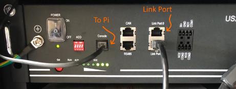
Console Out – Raspberry Pi
The console port demarcated “Console” must be utilised as the output to the raspberry pi. It goes into an available USB port on the Pi.
Dip Switches
Unless you have multiple banks/stacks of Pylon, ALL dip switches must remain down. A single master can control 7 slaves meaning 8 units per bank/stack. Thus, unless you have more units than this on the banks the master will be responsible for auto assigning the slaves and setting the baud rate.
Inverter Uptakes
Positioning of the inverter uptakes is critical to the overall operation of the system. Typically, the master pylon would supply the Positive (orange) uptake and the last slave would supply the Negative (Black) uptake. They are interchangeable, meaning that the last slave can supply the Positive (orange) and the master pylon the Negative (black), but they must be positioned on either side of the battery without exception.
Use of Raspberry Pi
The Axpert 5VA and MKS II must use the centurion solar raspberry pi in order to allow the inverter to correctly sense the batteries SOC. This is especially relevant for deep cycling of the battery and heavy loading on the inverter. Centurion solar have also provided the raspberry pi with ability to control the Axperts as well, this enables “dial in” or remote maintenance to take place. The Raspberry Pi is not critical for use in the Infini series since the Infini has more custom setting for battery control and is less dependant on prestored lead acid settings. That said, the Pi does allow for excellent reporting on the infini series and enables early system diagnosis for installers and maintenance crews.
Axpert 5kVA and MKS II settings
Note that this is preferably done on the watchpower program but can of course be achieved through inverter console keyboard. The settings enabling it to work with
Setting 1: SOL – Solar First
Setting 2: Charging Current: 25Amp per Pylon
Setting 5: Use – User Defined
Setting 12: 48V – Back to Grid
Setting 13: 51V – Back to Battery
Setting 16: OSO – Solar as only charger
Setting 26: 53.2V – Bulk Charge Voltage
Setting 27: 53.2V – Float Charge Voltage
Setting 29: 47.5V- Battery Cut Out
*Note -Setting 1 and 16 would typically be adjusted in times of frequent load shed, under this setting the solar panels are doing all the charging which may not be sufficient charge back to battery in times of frequent load shedding.
Infini Series
The most important settings on the infini are as follows- Select Parameter Settings:
Bulk Voltage: 53.2V
Float Voltage: 53.2V
Charging Current: 25Amp per Pylon
Battery cut off discharging when grid is available: 48V
Battery re-discharging when grid is available: 51V
Battery cut off discharging when grid unavailable: 47V
Battery re-discharging when grid is unavailable: 50V
*Note – some of these settings will need to be adjusted during times of load shedding. This is more based around preservation of battery storage in time of grid availability.
This is an application document that will be updated to be more comprehensive, additional documents relating to installation tips and trouble shooting will be published in the coming day.
Jason Sole – Renewable Designer – Megasolar SA